
Copyright © 2024 Kees Krijnen
SR2CB
Introduction
The Synchronous Redundant Ring Channel Bus (S-R-square-C-Bus) is a data bus with a open ring topology where a data channel is constructed from successive frames fixed bit/bits/byte/word/dword/qword/etc. positions. The SR2CB network protocol supports synchronous operation by means of a distributed clock mechanism. Each ring node has two full duplex (TX/RX) hardware ports.
The physical interface (layer) between SR2CB nodes is based on 1000BASE-T, 100BASE-TX, RS-485 or LVDS. 1000BASE-T and 100BASE-TX PHYs are also common for the ethernet network physical layer but not bound to transmit solely ethernet frames. The SR2CB frames are continuously transmitted by the ring nodes clockwise and counterclockwise. Slave nodes retransmit those SR2CB frames after receipt and insert or extract channel data 'on the fly'. Within a SR2CB master/slave ring the single master node starts the redundant ring initialization and transmits the SR2CB frames. Master nodes do not pass SR2CB frames around except for a broken redundant ring (single point of failure) or when the redundant ring is exclusively build from master nodes. Downloads are located at github.com/krynentechnology/sr2cb.
Contents
Network
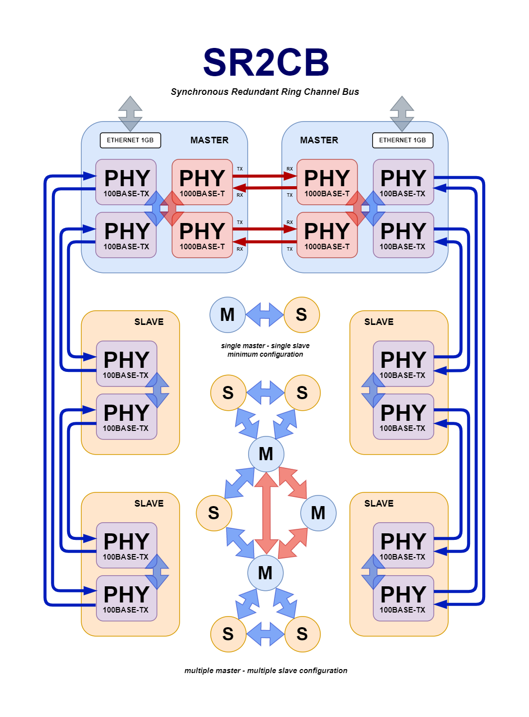
A minimum SR2CB system configuration consist of a single master and a single slave. The number of slave nodes could be extended to a maximum of 8192 slave nodes for each master/slave ring. Each node has a packet propagation delay of about 0.5 us, so a ring with the maximum number of nodes has a total delay of ~4 ms. This is the maximum packet delay between the slave nodes adjacent to the master (counter and counterclockwise first ring node position). Multiple SR2CB master devices could assemble a ring where data channels from different master/slave ring configurations could be shared.
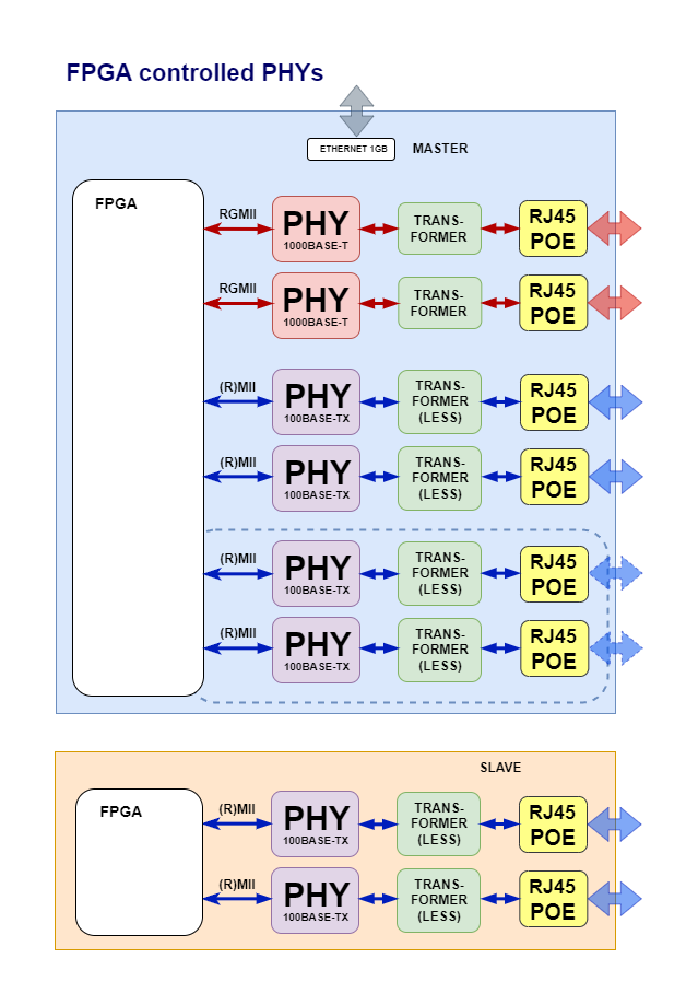
Master nodes might have a separate ethernet port. 1000BASE-T and 100BASE-TX PHYs full duplex ports could be controlled by an FPGA. PHY RGMII interface setup reduces the number of PCB traces for the 1000BASE PHY. The interface setup for 100BASE-TX PHY is (R)MII.
Packets and frames
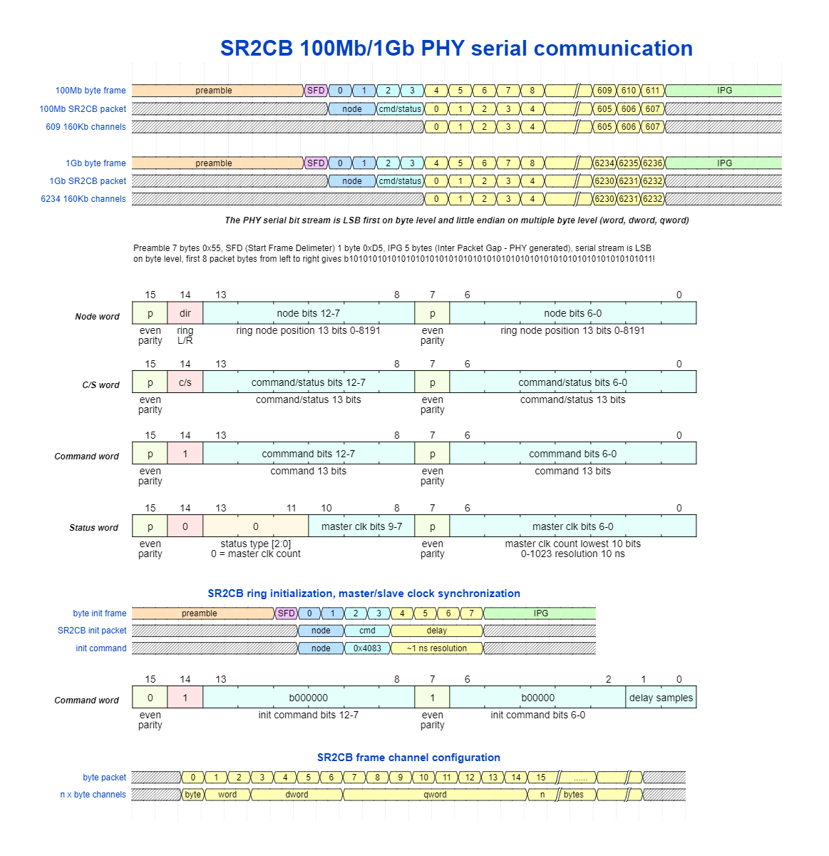
The number of SR2CB frames per second depends on the frame packet size which for the 'ethernet' PHYs starts with a SFD (Start Frame Delimeter) byte preceding by seven preamble bytes and ends with an IPG (Idle Packet Gap) sequence of five bytes. An audio application 20k SR2CB frames per second gives a byte channel speed of 160kb/s (20k times 8 bits) and offers 608 byte channels for 100BASE-TX and 6233 byte channels for 1000BASE-T PHYs. For the 1000BASE-T PHYs stable jumbo frames support is assumed, otherwise smaller frame sizes should be applied where some upper bits from the node position could indicate a frame ID. The 160kb/s is high enough for good audio quality APCM (32kHz voice - low latency - described in the Bluetooth A2DP specification) and Opus (48kHz voice and music) codecs - if required AES encrypted and authenticated.
Clock synchronization
The master/slave nodes clock synchronization starts when all devices are powered up and (redundant) physical links have been established. The SR2CB master sends a clock synchronization command to one of the adjacent (ring clockwise or counterclockwise) connected slave nodes and counts the delay (10ns resolution) until this slave node returns this message (TX/RX data valid signal). This command could be sent repeated two, four or eight times; each time after the RX data valid signal is low again. The calculated delay is the delay count divided by 2 times the number of delay samples (1, 2, 4 or 8) and sent to the slave node with a clock sync delay set command. The delay sent is a 28-bit 24.4 fractional value where the upper 24-bit represent the determined 10ns resolution delay. The slave node also returns this delay set message and stops returning received (clock sync) command messages afterwards, but will start passing status messages received from slave nodes with higher node positions. All messages returned by slave nodes are status messages, the command bit in the C/S word has been reset.
The SR2CB master continues sending a clock sync delay set command to the adjacent node (ring clockwise or counterclockwise) until all slave nodes have replied with a delay set status message. The master determines the last slave node by checking the slave node positions in the returned messages. The master receives messages from both RX ports (passed command and returned status messages). When the returned slave node position does not increment anymore, this node position indicates the last slave node position in the open ring. The received command messages from the other RX port directly indicate the number of slave nodes. When a slave node could not establish a physical link with its own adjacent node, it flips the direction bit (ring L/R) in the returned node word, indicating a broken ring. This is also clear when the master receives no command messages from the other RX port (or this TX/RX port could not establish a physical link).
Each of the slave nodes determine the delay to the adjacent node by passing the master clock synchronization command messages, count the delay until the adjacent node returns the message and calculate the delay as the SR2CB master does. The clock sync delay set command is sent to the adjacent node when its own delay (delay time from master) has been set and the delay to the adjacent node has been calculated. Each slave node adds the calculated delay to the delay set before it sends the clock sync delay set command to the adjacent node.
When the SR2CB master has collected the delays set from all slave nodes from one ring direction (clockwise or counterclockwise) it starts collecting the slave node delays set from the other ring direction. Each slave node provides two different delays set (except when there is a single slave node), depending on which master ring port the clock sync commands are received from. The SR2CB master sends a clock reset command to both rings when the delays set have been collected from both rings and resets its own 10ns resolution clock counter. Each slave node has two internal 68-bit (64.4 fractional - the 64 bit represents 10ns resolution) clock counters, one for each RX port. Those counters are reset on receipt of the clock reset command message.
The master/slave node clock crystals have an accuracy of generally 50ppm or better. Multiple 100Mhz clock crystals could deviate a maximum clock count of 5000 in one second (50ppm - 50*100). This means that the SR2CB master clock status message which represent the lowest 10 bits of the master clock counter, should be sent at least once in 100ms (in both ring directions). In practice the SR2CB master clock count status message will be sent when no other C/S messages are sent. The slave nodes two counter values (ring L/R) added with the delays set should match the master clock counter value. On receipt of the master clock status message slave nodes calculate the difference with their two clock values and start adding 9-15 when their clock count value is higher than the master clock, or adding 17-23 when their clock count value is lower than the master clock. This adding of a 5-bit 1.4 fractional value (9-23) stabilizes to an optimal value (around 16) for each 10ns increment of the internal 10ns resolution 64.4 bit clock counters. A filter is applied to prevent oscillation.
In the above SR2CB protocol the command/status field is represented by one word (2 bytes). When the command/status field is represented by five words (10 bytes), it would allow the master to send the full 64-bit master clock value. It would decrease the available number of byte channels by eight.